Direct Sequence Spread Spectrum
Published:
This post covers WIRELESS COMMUNICATIONS AND NETWORKS by William Stallings.
Basic Ideas
Direct Sequence Spread Spectrum (DSSS)
- For direct sequence spread spectrum (DSSS), each bit in the original signal is represented by multiple bits in the transmitted signal, using a spreading code.
- The spreading code spreads the signal across a wider frequency band in distinct proportion to the number of bits used.
- Therefore, a 10-bit spreading code spreads the signal across a frequency band that is 10 times greater than a 1-bit spreading code.
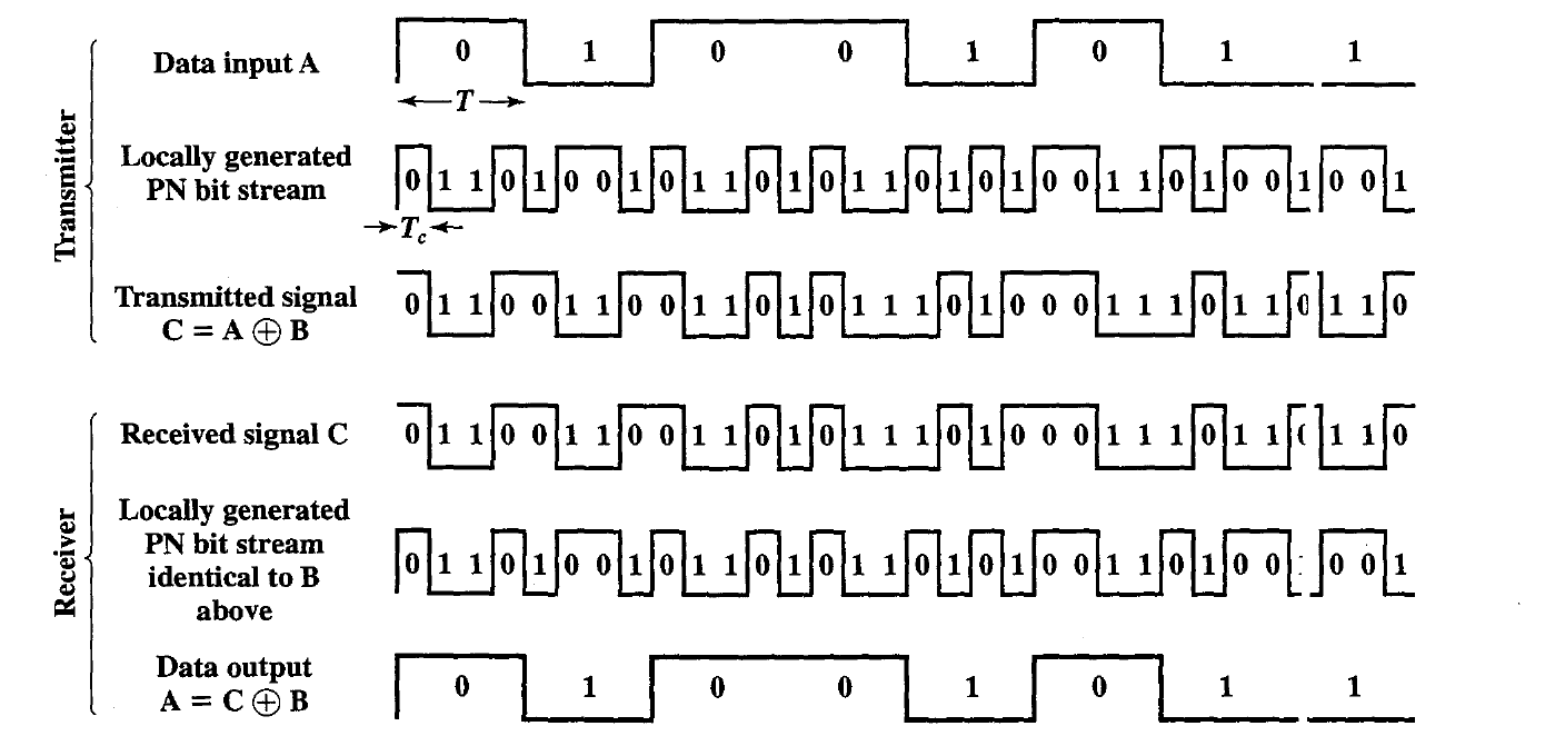
- One technique for direct sequence spread spectrum is to combine the digital information stream with the spreading code bit stream using an e {exclusive-OR (XOR).
- The XOR obeys the following rules:
- Note that an information bit of xor inverts the spreading code bits in the combination, while an information bit of zero causes the spreading code bits to be transmitted without inversion.
- The combination of stream has the data rate of the original spreading code sequence, so it has a wide bandwidth than the information stream.
- In this example, the spreading code bit Stream is clocked at four times the information rate.
DSSS Using BPSK
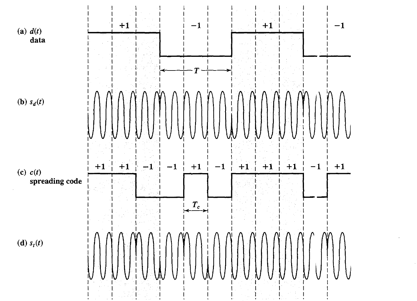
Rather than represent binary data with 1 and 0, it is more convenient for our purposes to use +1 and -1 to represent the two binary digits.
In that case, a BPSK signal can be represented as was shown in Equation
\(s_d(t)= Ad(t)cos(2 \pi f_ct)\\\) where
$A$ = amplitude of signal
$f_c$ = carrier frequency
$d( t)$ = the discrete function that takes on the value of +1 for one bit time if the corresponding bit in the bit stream is 1 and the value of -1 for one bit time if the corresponding bit in the bit stream is 0
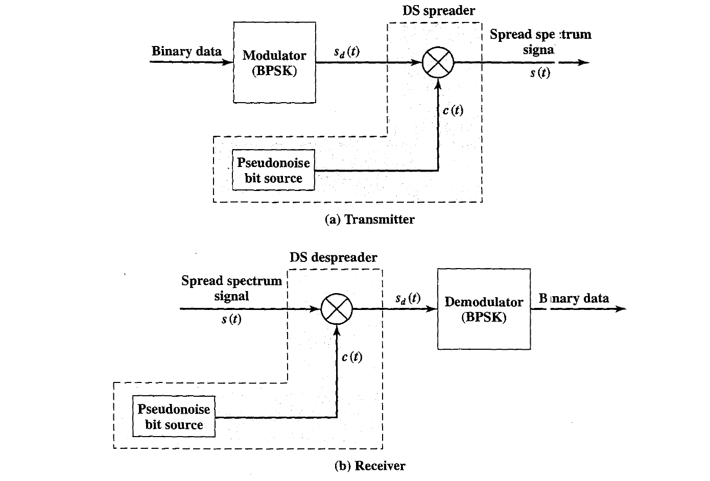
To produce the DSSS signal, we multiply the preceding by $c(t)$, which is the PN sequence taking on values of +1 and -1: \(s(t)= Ad(t)c(t)cos(2 \pi f_ct)\\ \\\) At the receiver, the incoming signal is multiplied again by e(t). But $ c(t) \times c(t)=1 $ and therefore the original signal is recovered: \(s(t)c(t)= Ad(t)c(t)cos(2 \pi f_ct)= s_d(t)\\\) Equation can be interpreted in two ways, leading to two diferent implementations. The first interpretation is to first multiply d(t) and c(t) together and then perform the BPSK modulation.
That is the interpretation we have bee n discussing. Alternatively, we can first perform the BPSK modulation on the data stream d(t) to generate the data signal Sd(t).
This signal can then be multiplied by c(t). An implementation using the second interpretation is shown in Figure.
DSSS Performance Considerations
- The spectrum spreading achieved by the direct sequence technique is easily determined
- In our example, the information signal has a bit width of T, which is equivalent to a data rate of $\frac{1}{T}$.
- In that case, the spectrum of tie signal, depending on the encoding technique, is roughly $2/T$. Similarly, the spectrum of the PN signal is $2/T_c$.
The resulting spectrum spreading. The amount of spreading that is achieved is a direct result of the data rate of the PN stream.
As with FHSS, we can get some insight into the performance of DSSS by looking at its effectiveness against jamming.
Let us assume a simple jamming signal at the center frequency of the DSSS system.
The jamming signal has the form \(s_j(t)= \sqrt{(2S_j)}cos(2 \pi f_ct)\\\)
\[s_r(t)= s(t)+s_j(t)+n(t)\]where
$s(t)$ = transmitted signal
$s_j(t)$ = jamming signal
n(t) = additive white noise
The despreader at the receiver multiplies $s_r(t)$ by $c(t)$, so the signal component due to the jamming signal is \(y_j(t) = \sqrt{2S_j}c(t)cos(2\pi f_ct)\)
This is simply a BPSK modulation of the carrier tone. Thus, the carrier power $S_j$ is spread over a bandwidth of approximately $\frac{2}{Tc}$.
However, the BPSK ,demodulator following the DSSS despreader includes a bandpass filter matched to the BPSK data, with bandwidth of $\frac{2}{T}$.
Thus, most of the jamming power is filtered.
Although a number of factors come into play, as an approximation, We can say that the jamming power passed by the filter is \(S_{jF} = S_j(\frac{2}{T})/(\frac{2}{T_c}) = S_j( \frac{T_c}{T})\)
The jamming power has been reduced by a factor of ($\frac{T}{T_c}$) through the use of spread spectrum. The inverse of this factor is the gain in signal-to-noise ratio: \(G_p = \frac{T}{T_c}=\frac{R_c}{R}=\frac{W_s}{W_d}\)

where $R_c$ is the spreading bit rate, $R$ is the data rate, $W_d$ is the signal bandwidth, and $W_s$ is the spread spectrum signal bandwidth. The result is similar to the result for FHSS.
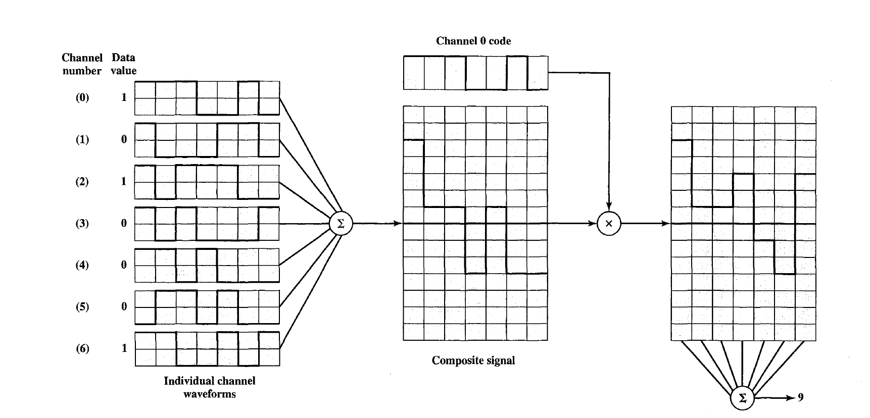
A simplified scheme for CDMA encoding and decoding. There are seven logical channels, all using DSSS with a spreading code of 7 bits. Assume that all sources are synchronized. If all seven sources transmit a data bit, in the form of a 7-bit sequence, the signals from all sources combine at the receiver so that two positive or two negative values reinforce and a positive and negative value cancel.
To decode a given channel, the receiver multiplies the incoming composite signal by the spreading code for that channel, sums the result, and assigns binary 1 for a positive value and binary 0 for a negative value.
a. What are the spreading codes for the seven channels?
b. Determine the receiver output measurement for channel and the bit value assigned.
c. Repeat part b for channel 2.
- For the spreading codes of the preceding problem, determine the cross correlation between channel 0 and each of the other 6 channels.