Frequency Hopping Spread Spectrum
Published:
This post covers WIRELESS COMMUNICATIONS AND NETWORKS by William Stallings.
Basic Ideas
- Frequency Hopping Spread Spectrum
With frequency hopping spread spectrum (FHSS), the signal is broadcast over a seemingly random series of radio frequencies, hopping from frequency to frequency at fixed intervals.
- A receiver, hopping between frequencies in synchronization with the transmitter, picks up the message.
- Would-be eavesdroppers hear only unintelligible blips. Attempts to jam the signal on one frequency succeed only It knocking out a few bits of it.
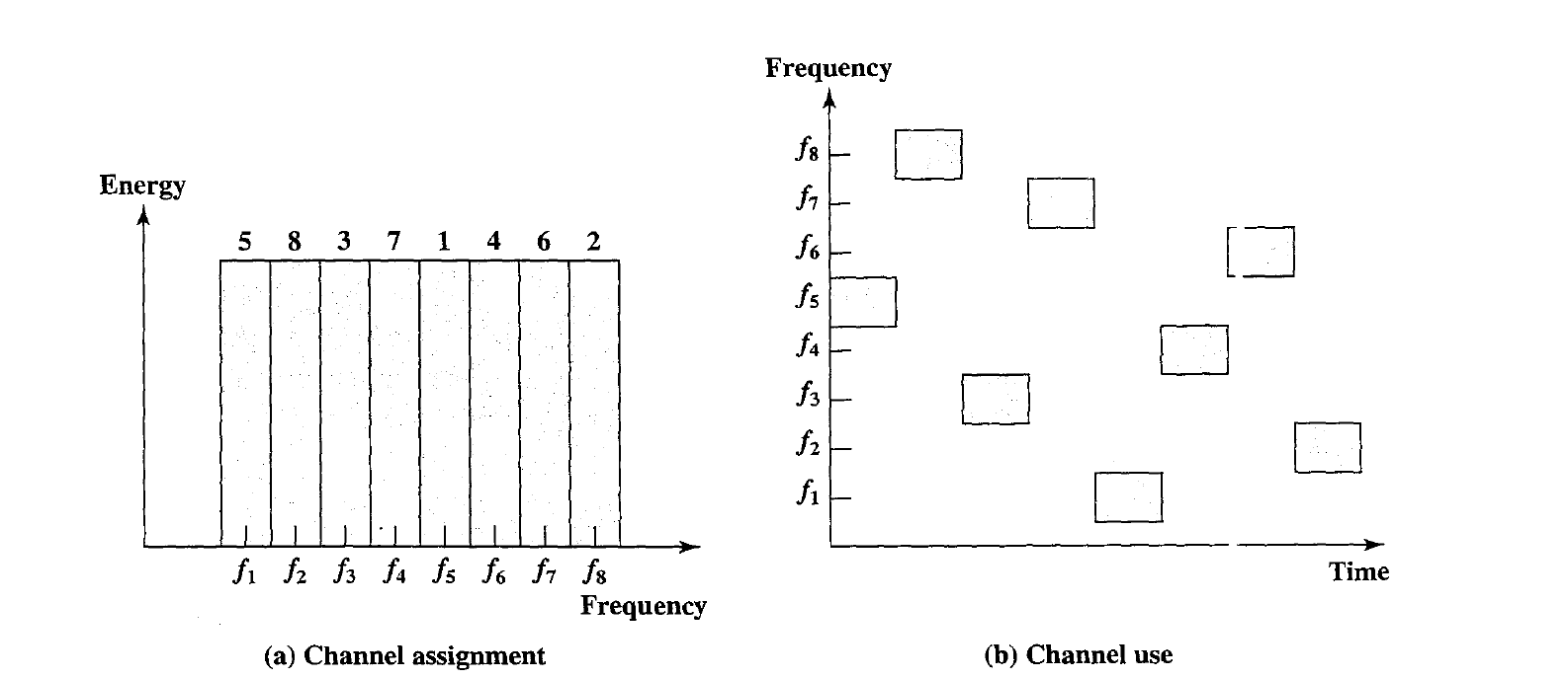
- Figure shows an example of a frequency hopping signal. A number of channels are allocated for the FH signal.
- Typically, there are $2^k$ carrier frequencies forming $2^k$ channels. The spacing between carrier frequencies and hence the width of each channel usually corresponds to the bandwidth of the input signal.
- The transmitter operates in one channel at a time for a fixed interval; for example, the: IEEE 802.11 wireless LAN standard uses a 300-ms interval. During that interval, some number of bits (possibly a fraction of a bit, as discussed subsequently) is transmitted using some encoding scheme.
- The sequence of channels used is dictated by a spreading code. Both transmitter and receiver use the same code to tune into a sequence of channels in synchronization.
- Each $k$ bits of the PN source specifies one of the $2^k$ carrier frequencies. At each successive interval (each k PN bits), a new carrier frequency c(t) is selected.
- This frequency is then modulated by the signal produced from the initial modulator to produce a new signal set with the same shape but now centered on the selected carrier frequency.
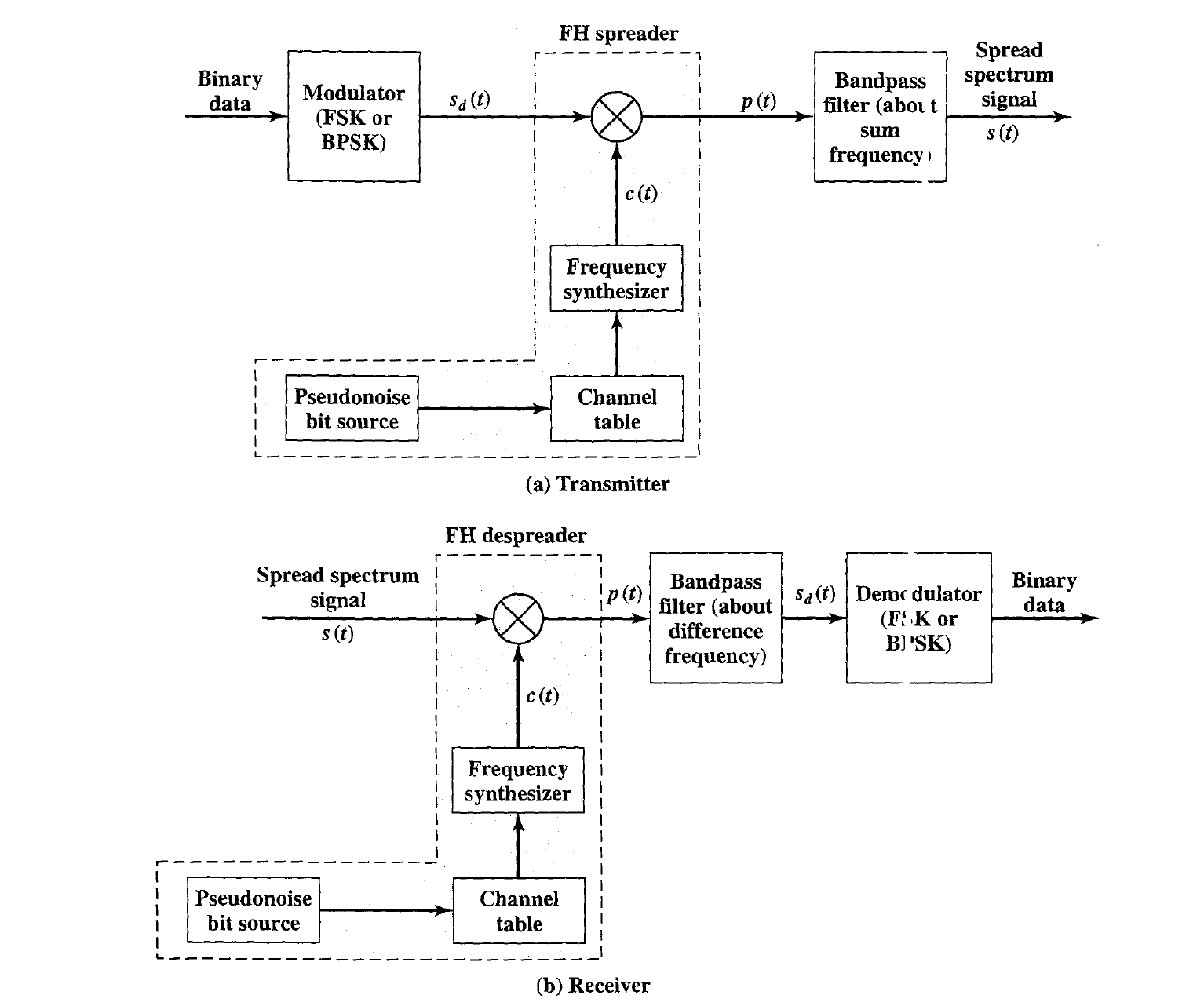
- On reception, the spread spectrum signal i; demodulated using the same sequence of PN-derived frequencies and then de modulated to produce the output data.
where $A$ = amplitude of signal, $f_0$ = base frequency , $b_i$ = value of the $i^{th}$ bit of data (+1 for binary 1, -1 for binary 0), $\Delta f$ = frequency separation , T = bit duration; data rate = $\frac {1}{T}$
Thus, during the $i^{th}$ bit interval, the frequency of the data signal is $f_0+ f_i$ if the data bit is -1 and $f_0 + \Delta f + f_i$ if the data bit is +1.
- The frequency synthesizer generates a constant-frequency tone whose frequency hops among a set of $2^k$ frequencies, with the hopping pattern be determined by k bits from the PN sequence.
- For simplicity, assume the duration of one hop is the same as the duration of one bit and we ignore phase differences between the data signal $S_d(t)$ and the spreading signal, also called a chipping signal, $c(t)$. Then the product signal during the $i^{th}$ hop (during the $i^{th}$ bit) is
A bandpass filter (Figure) is used to block the difference frequency and pass the sum frequency, yielding an FHSS signal of \(s(t) = 0.5A cos(2\pi (f_0 + 0.5(b_i + 1)\Delta f + f_i)t)\)
Thus, during the $i^{th}$ bit interval, the frequency of the data signal is $f_0$ if the data bit is -1 and $f_0 + \Delta f$ if the data bit is +1. \(p(t)) = s(t)c(t) = 0.25A [cos(2\pi (f_0 + 0.5(b_i + 1)\Delta f + f_i)t)+cos(2\pi (f_0+0.5 (b_i+1)\Delta f)t)]\) At the receiver, a signal of the form $s(t)$ just defined will be received. This is multiplied by a replica of the spreading signal to yield a product signal of the form. A bandpass filter (Figure) is used to block the sum frequency and pass the difference frequency, yielding a signal of the form of $S_d(t)$ \(0.25A cos( 2 \pi (f_o + 0.5(b_i + 1)\Delta f )t)\)
FHSS Using MFSK
A common modulation technique used in conjunction with FHS is multiple FSK (MFSK). Recall that MFSK uses $M = 2^L$ different frequencies to encode the digital input L bits at a time. The transmitted signal is of the form
\[s_i(t) = A cos 2 \pi f_i t\] \[f_i = f_c + (2i - 1 - M)f_d\]$f_c$ = denotes the carrier frequency, $f_d$ = denotes the difference frequency, M = number of different signal elements = $2^L$ and L = number of bits per signal elements

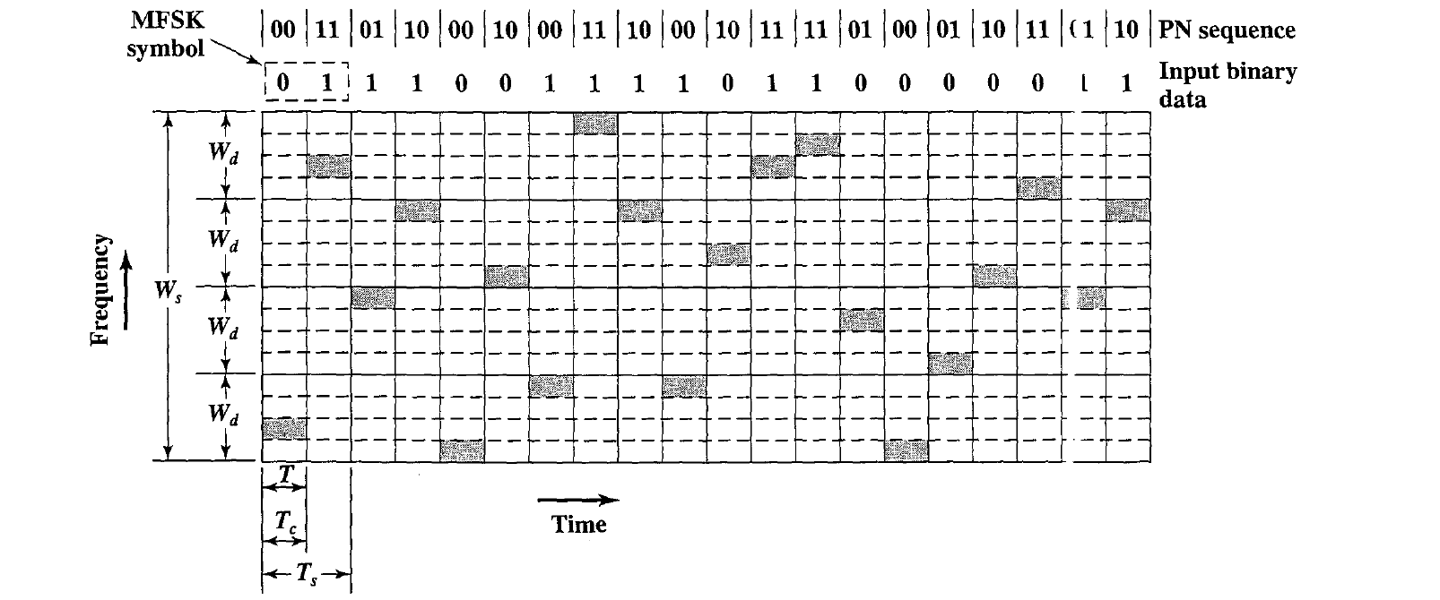
Figure shows an example of slow FHSS, using the MFSK. That is, $M = 4$, and the same sequence of input bits is used in both examples. The display in the figure shows the frequency transmitted ( y-axis) as a function of time (x-axis). Each column represents a time unit $T_s$ in which a single 2-bit signal element is transmitted.
- The shaded rectangle in the column ind cates the frequency transmitted during that time unit.
- Each pair of columns corresponding to the selection of a frequency band based on a 2-bit PN sequence. Thus, for the first pair of columns, governed by PN sequence 00, the lowest band of frequencies is used. For the second pair of columns, governed by PN sequence 11, the highest band of frequencies is used.
- Here we have $M = 4$, which means that four different frequencies are used to encode the data input 2 bits at a time.
- Each signal element is a discrete frequency tone, and the total MFSK bandwidth is $W_d = M f_d$ We use an FHSS scheme with $k = 2$.
- That is, there are $4 = 2^k$ different channels, each of width $W_d$.
- The total FHSS bandwidth is $W_s = 2^kW_d$
- Each $2$ bits of the PN sequence is used to select one of the four channels.
- That channel is held for a duration of two signal elements, or four bits ($T_c = 2T_s = 4T$).
- Figure shows an example of fast FHSS, using the same MFSK example.
- Again, $M = 4$ and $k = 2$. In this case, however, each signal element is represented by two frequency tones.
- Again, $W_d = Mf_d$ and $W_s = 2^kW_d$. In this example $T_s = 2T_c = 2T$. In general, fast FHSS provides improved performance :ompared to slow FHSS in the face of noise or jamming.
- For example, if $3$ or more frequencies (chips) are used for each signal element, the receiver can decide which signal element was sent on the basis of a majority of the chips being correct.
FHSS Performance Considerations
- Typically, a large number of frequencies are used in FHSS so that $W_s$ is much larger than $W_d$.
- One benefit of this is that a large value of k results in a systen, that is quite resistant to noise and jamming. For example, suppose we have an MFSK transmitter with bandwidth $W_d$ and noise jammer of the same bandwidth and fixed power $S_j$ on the signal carrier frequency.
- Then we have a ratio of signal energy per bit to noise power density per Hertz of
- If frequency hopping is used, the jammer must jam all $2^k$ frequencies. With a fixed power, this reduces the jamming power in anyone frequency band to $S _j/2^k$ . The gain in signal-to-noise ratio, or processing gain, is
- An FHSS system employs a total bandwidth of $W_s = 400$ MHz and an individual channel bandwidth of 100 Hz. What is the minimum number of PN bits required for each frequency hop?
- An FHSS system using MFSK with M = 4 employs 1000 different frequencies. What is the processing gain?
The following table illustrates the operation of an FHSS system for one complete
period of the PN sequence.
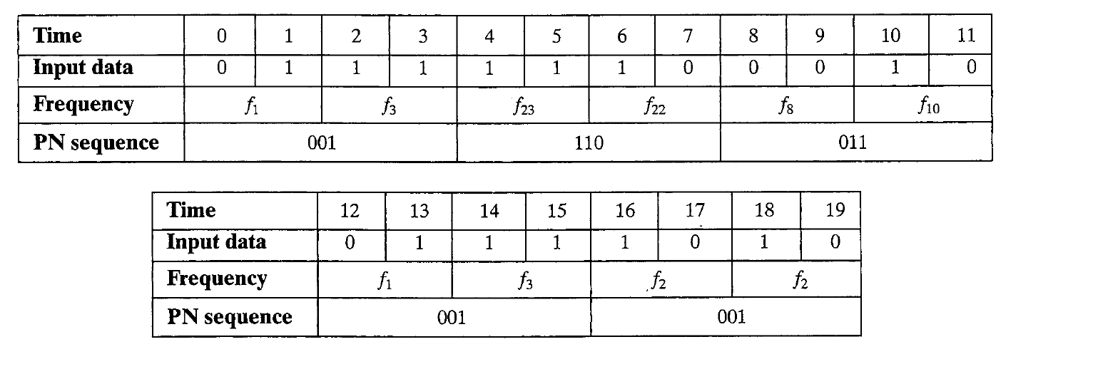
- a. What is the period of the PN sequence?
- b. The system makes use of a form of FSK. What form of FSK is it?
- c. What is the number of bits per symbol?
- d. What is the number of FSK frequencies?
- e. What is the length of a PN sequence per hop?
- f. Is this a slow or fast FH system?
- g. What is the total number of possible hops?
- h. Show the variation of the dehopped frequency with time.
Consider an MFSK scheme with $f_c = 250$ kHz, $f_d = 25$ kHz, and $M = 8 (L = 3 ~ bits)$.
a. Make a frequency assignment for each of the eight possible 3-bit data combinations.
b. We wish to apply FHSS to this MFSK scheme with k = 2; that is, the system will hop among four different carrier frequencies. Expand the results of part (a) to show the 4 x 8 = 32 frequency assignments.