PN Sequences
Published:
This post covers WIRELESS COMMUNICATIONS AND NETWORKS by William Stallings.
Basic Ideas
- The spreading sequence, $c(t)$, is a sequence of binary digits shared by transmitter and receiver.
- Spreading consists of multiplying, $(XOR)$ the input data by the spreading sequence, where the bit rate of the spreading sequence is higher than that of the input data.
- When the signal is received, the spreading is removed by multiplying with the same spreading code, exactly synchronized with the received signal.
- The resulting data rate is consequently that of the spreading sequence. This increases the transmitted data rate and therefore increases the required bandwidth.
- The spreading codes are chosen so that the resulting signal is noiselike; therefore, there should be an approximately equal number of ones and zeros in the spreading code and few or no repeated patterns.
- When spreading codes are used in a CDMA application there is the further requirement of lack of correlation. When multiple signals are received, each spread with a different spreading code, the receiver should be able to pick out any individual signal using that signal’s spreading code.
- The spread signal should behave as if they were uncorrelated with each other, so that other signals will appear as noise and not interfere with the despreading of a particular signal.
- Because of the high degree of redundancy provided by the spreading operation, the despreading operation is able to cope with the interference of other signals in the same bandwidth.
PN Sequences
- An ideal spreading sequence would be a random sequence of binary ones and zeros.
- However, because it is required that transmitter and receiver must have a copy of the random bit stream, a predictable way is needed to generate the same bit stream at transmitter and receiver and yet retain the desirable properties of a random bit stream.
- This requirement is met by a PN generator. A PN generator will produce a periodic sequence that eventually repeats but that appears to be random.
The period of a sequence is the length of the sequence before it starts repeating.
- PN sequences are generated by an algorithm using some initial value called the seed.
- The algorithm is deterministic and therefore produces sequences (If numbers that are not statistically random.
- However, if the algorithm is good, the resulting sequences will pass many reasonable tests of randomness.
- Such numbers are often referred to as pseudorandom numbers, or pseudonoise sequences.
- An important point is that unless you know the algorithm and the seed, it is impractical to predict the sequence.
- Hence, only a receiver that shares this information with a transmitter will be able to decode the signal successfully.
PN Properties
- The sequence of numbers be random in some well-defined statistical sense. The following two criteria are used to validate that a sequence of numbers is random:
- Uniform distribution: The distribution of numbers in the sequence should be uniform; that is, the frequency of occurrence of each of the numbers should be approximately the same.
Correlation property: If a period of the sequence is compared term by term with any cycle shift of itself, the number of terms that are the same differs from those that are different by at most 1.
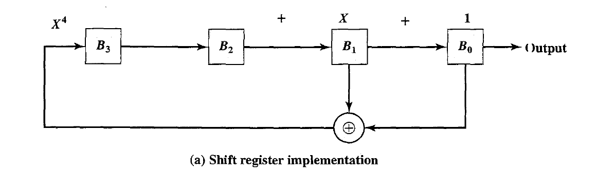
- Linear Feedback Shift Register Implementation

- The PN generator for spread spectrum is usually implemented as a circuit consisting of $XOR$ gates and a shift register, called a linear feedback shift register $(LFSR)$.
- The LFSR is a string of 1-bit storage devices. Each device has an output line, which indicates the value currently stored, and an input line.
- At discrete time instants, known as clock· times, the value in the storage device is replaced by the value indicated by its input line, The entire LFSR is clocked simultaneously, causing a I-bit shift along the entire register.
- Two equivalent ways of characterizing the PN LFSR are used. We can think of the generator as implementing a sum of XOR terms:
- The shift register technique has several important advantages. The sequences generated by an LFSR can be nearly random with long periods, which aids in making the spread signal appear noiselike. In addition, LFSRs are easy to implement in hardware and can run at high speeds; this is important because the spreading rate is higher than the data rate.
- It can be shown that the output of an LFSR is periodic with maximum period $N = 2^n - 1$. The all-zeros sequence occurs only if either the initial contents of the LFSR are all zero or the coefficients in Equation are all zero(no feedback).
- These sequences are called maximal-length sequences, or m-sequences. The m-sequences are important in enabling synchronization by the receiver and in USE in multiple access techniques, such as CDMA, as will be explained.
- A feedback configuration can always be found that gives a period of N; the resulting
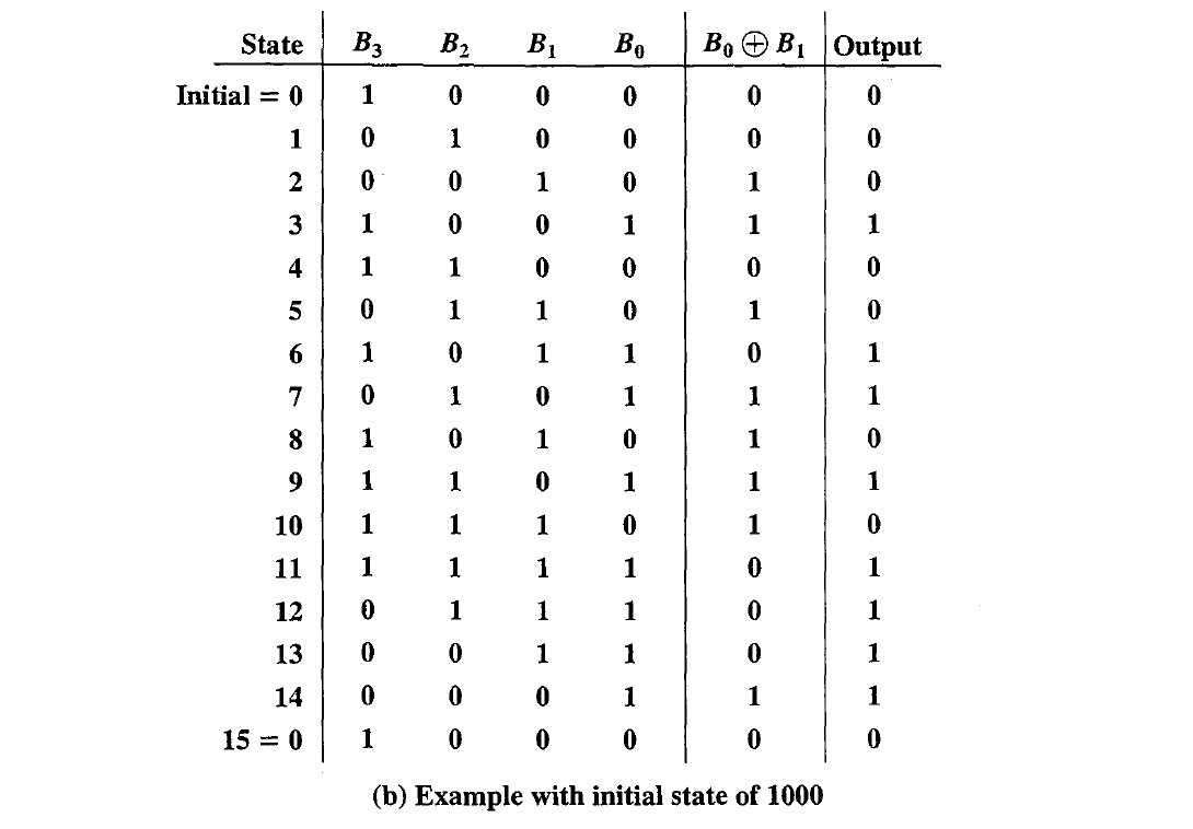
- With each different initial state, the m-sequence begins at a different point in its cycle, but it is the same sequence.
Properties of m-sequences
- An m-sequence has $2^n - 1$ ones and $2^n - 1$ zeros.
- If we slide a window of length $n$ along the output sequence for N shifts, where $N = 2^n - 1$, each n-tuple, except the all-zero sequence, appears exactly once.
- There is one run of ones of length n; one run of zeros of length n - 1; one run of ones and one run of zeros of length n - 2; two runs of ones and two runs of zeros of length n - 3; and, in general, $2^n -3$ runs of ones and $2^n- 3$ runs of zeros of length 1.
- We define the periodic autocorrelation of the resulting sequences as
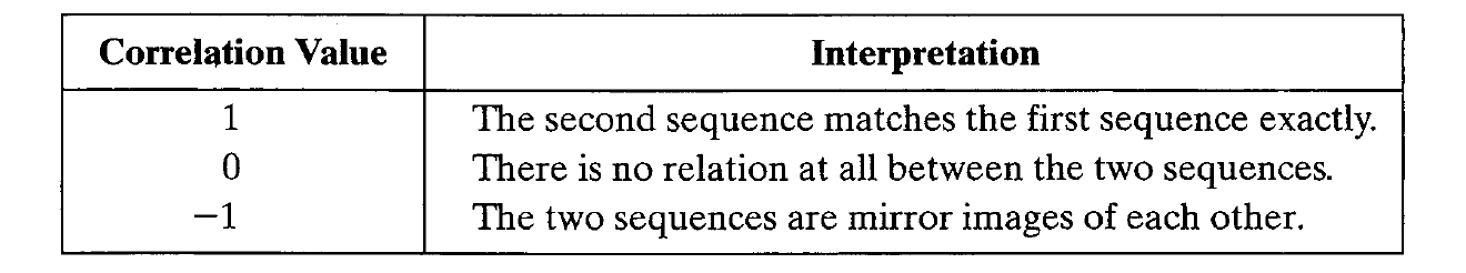
- In essence, correlation is the concept of determining how much similarity one set of data has with another. Correlation is defined with a range between -1 and 1 with the following meanings:
- Other values indicate a partial degree of correlation. Autocorrelation, which is defined, is the correlation of a sequence with all phase shifts of itself.
- Pure random data should have a correlation value close to 0 for all autocorrelations with a phase shift other than 0.
The m-sequences have this property. It can be shown that the autocorrelation function of an m-sequence, with its single sharp peak, is a powerful aid to synchronization by the receiver.
A related function, also important in the spread spectrum context, is the cross correlation function. In this case, the comparison is made between two sequences from different sources rather than a shifted copy of a sequence with itself. The cross correlation between two sources,A and B, is defined as: \(R_{A,B}(\tau) = \frac{1}{N} \Sigma^{k=N}_{k=1} A_k B_{k- \tau}\)
In general, the cross correlation value produced by matching a sequence with a random sequence is low, which has two advantages:
\1. The cross correlation between an m-sequence and noise is low, and this property is useful to the receiver in filtering out noise.
\2. The cross correlation between two different m-sequences is low, and this property is useful for CDMA applications because it enables a receiver to discriminate among spread spectrum signals generated by different m-sequences.
This problem demonstrates that different LFSRs can be used to generate an m-sequence.

a. Assume an initial state of 10000 in the LFSR of Figure a. show the generation of an m-sequence.
b. Now assume the configuration of Figure b, with the same initial state, and repeat part a. Show that this configuration also produces an m-sequence, but that it is a different sequence from that produced by the first LFSR.
Consider a CDMA system in which users A and B have the Walsh codes
(-1 1 -11 -1 1 -11) and (-1 -111 -1 -111), respectively.
a. Show the output at the receiver if A transmits a data bit 1 and B does not transmit.
b. Show the output at the receiver if A transmits a data bit 0 and B does not transmit.
c. Show the output at the receiver if A transmits a data bit 1 and B transmits a data bit 1. Assume the received power from both A and B is the same.
d. Show the output at the receiver if A transmits a data bit 0 and B transmits a data bit 1. Assume the received power from both A and B is the same.
e. Show the output at the receiver if A transmits a data bit 1 and B transmits a data bit O. Assume the received power from both A and B is the same.
f. Show the output at the receiver if A transmits a data bit 0 and B transmits a data bit O. Assume the received power from both A and B is the same.
g. Show the output at the receiver if A transmits a data bit 1 and B transmits a data bit 1. Assume the received power from B is twice the received power from A. This can be represented by showing the received signal component from A as consisting of elements of magnitude 1(+1, -1) and the received signal component from B as consisting of elements of magnitude 2 (+2, - 2).
h. Show the output at the receiver if A transmits a data bit 0 and B transmits a data bit 1. Assume the received power from B is twice the received power from A.