Cellular Network Organization
Published:
This post covers Wireless Communications: Principles and Practices by Theodore S. Rapport.
Basic Ideas
- The Cellular Concept- Fundamental System Design
- Cellular technology is the foundation of mobile wireless communications and supports users in locations that are not easily served by wired networks.
- Cellular technology is the underlying technology for mobile telephones, personal communications systems, wireless Internet and wireless Web applications, and much more.
- Cellular Network Organization

- Figure shows the principal elements of a cellular system. In the approximate center of each cell is a base station (BS). The BS includes an antenna, a controller, and a number of transceivers, for communicating on the channels assigned to that cell.
- The controller is used to handle the call process between the mobile unit and the rest of the network.
- At any time, a number of mobile units may be active and moving about within a cell, communicating with the BS.
- Each BS is connected to a mobile telecommunications switching office (MTSO), with one MTSO serving multiple BSs.
- Typically, the link between an MTSO and a BS is by a wire line, although a wireless link is also possible. The MTSO connects calls between mobile units.
- The MTSO is also connected to the public telephone or telecommunications network and can make a connection between a fixed subscriber to the public network and a mobile subscriber to the cellular network.
- The MTSO assigns the voice channel to each call, performs handoffs (discussed subsequently), and monitors the call for billing information.
- The use of a cellular system is fully automated and requires no action on the part of the user other than placing or answering a call.
- Two types of channels are available between the mobile unit and the base station (BS): control channels and traffic channels.
- Control channels are used to exchange information having to do with setting up and maintaining calls and with establishing a relationship between a mobile unit and the nearest BS.
- Traffic channels carry a voice or data connection between users.
- Figure illustrates the steps in a typical call between two mobile users within an area controlled by a single MTSO:
- Mobile unit initialization: When the mobile unit is turned on, it scans and selects the strongest setup control channel used for this system (Figure).
- Cells with different frequency bands repetitively broadcast on different setup channels.
- The receiver selects the strongest setup channel and monitors that channel.
- The effect of this procedure is that the mobile unit has automatically selected the BS antenna of the cell within which it will operate.
- Then a handshake takes place between the mobile unit and the MTSO controlling this cell, through the BS in this cell.
- The handshake is used to identify the user and register its location. As long as the mobile unit is on, this scanning procedure is repeated periodically to account for the motion of the unit.
- If the unit enters a new cell, then a new BS is selected. In addition, the mobile unit is monitoring for pages, discussed subsequently.
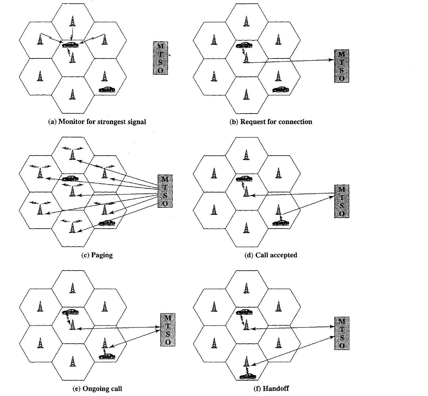
Mobile-originated call: A mobile unit originates a call by sending the number of the called unit on the preselected setup channel (Figure).
The receiver at the mobile unit first checks that the setup channel is idle by examining information in the forward (from the BS) channel.
When an idle is detected, the mobile unit may transmit on the corresponding reverse (to BS) channel. The BS sends the request to the MTSO.
Paging: The MTSO then attempts to complete the connection to the called unit.
The MTSO sends a paging message to certain BSs depending on the called mobile unit number (Figure).
Each BS transmits the paging signal on its own assigned setup channel.
Call accepted: The called mobile unit recognizes its number on the setup channel being monitored and responds to that BS, which sends the response to the MTSO.
The MTSO sets up a circuit between the calling and called BSs.
At the same time, the MTSO selects an available traffic channel within each BS’s cell and notifies each BS, which in turn notifies its mobile unit (Figure).
The two mobile units tune to their respective assigned channels.
Ongoing call: While the connection is maintained, the two mobile units exchange voice or data signals, going through their respective BSs and the MTSO (Figure).
Handoff: If a mobile unit moves out of range of one cell and into the range of another during a connection, the traffic channel has to change to one assigned to the BS in the new cell (Figure).
The system makes this change without either interrupting the call or alerting the user.
Other functions performed by the system but not illustrated in Figure 10.6
include the following:
Call blocking: During the mobile-initiated call stage, if all the traffic channels assigned to the nearest BS are busy, then the mobile unit makes a preconfigured
number of repeated attempts. After a certain number of failed tries, a
busy tone is returned to the user.
Call termination: When one of the two users hangs up, the MTSO is informed and the traffic channels at the two BSs are released.
Call drop: During a connection, because of interference or weak signal spots in certain areas, if the BS cannot maintain the minimum required signal strength for a certain period of time, the traffic channel to the user is dropped and the MTSO is informed.
Calls to/from fixed and remote mobile subscriber: The MTSO connects to the public switched telephone network. Thus, the MTSO can set up a connection between a mobile user in its area and a fixed subscriber via the telephone network.
Further, the MTSO can connect to a remote MTSO via the telephone network or via dedicated lines and set up a connection between a mobile user in its area and a remote mobile user.
Mobile Radio Propagation Effects
Signal strength: The strength of the signal between the base station and the mobile unit must be strong enough to maintain signal quality at the receiver but not so strong as to create too much cochannel interference with channels
in another cell using the same frequency band. Several complicating factors exist. Human-made noise varies considerably, resulting in a variable noise
level.
- For example, automobile ignition noise in the cellular frequency range is greater in the city than in a suburban area.
- Other signal sources vary from place to place. The signal strength varies as a function of distance from the BS to a point within its cell. Moreover, the signal strength varies dynamically as the mobile unit moves.
- Fading: Even if signal strength is within an effective range, signal propagation effects may disrupt the signal and cause errors.
- In designing a cellular layout, the communications engineer must take account of these various propagation effects, the desired maximum transmit power level at the base station and the mobile units, the typical height of the mobile unit antenna, and the available height of the BS antenna.
- These factors will determine the size of the individual cell.
where $f_c$ = carrier frequency in MHz from 150 to 1500 MHz
$h_t$ = height of transmitting antenna (base station) in m, from 30 to 300 m
$h_r$ = height of receiving antenna (mobile unit) in m, from 1 to 10 m
d = propagation distance between antennas in km, from 1 to 20 km
$A(h_r)$ = correction factor for mobile unit antenna height
For a small or medium sized city, the correction factor is given by \(A(h_r) = (1.1logf_c - 0.7)h_r - (1.56logf_c - 0.8) dB \\\) And for a large city it is given by
\(A(h_r) = 8.29[1og(1.54 h_r)]^2 - 1.1 dB ~~~~~ for ~ f_c \leq 300 MHz\\\)
To estimate the path loss in a suburban area, the formula for urban path loss in Equation is modified as \(L_{dB}(suburban) = L_{dB}(urban) - 2[1og(f_c/28)]^2 - 5.4 \\\)
\[L_{dB}(open) = L_{dB}(urban) - 4.78(1ogf_c)^2 - 18.733(1ogf_c) - 40.98\\\]- Let $f_c = 900 MHz$, $h_t=40m$, $h_r =5 m$, and $d=10 km$. Estimate the path loss for medium-size city