LTE-A
Published:
This post covers Mobile and Wireless Networks by Khaldoun Al Agh, Guy Pujolle, and Tara Ali-Yahiya.
Basic Ideas
Fundamentals of the MAC layer in LTE
- The important feature of the MAC layer in LTE eNB is to offer RRC functionalities related to the control plane. It achieves different functions: RRM admission control, scheduling and enforcement of negotiated QoS, cell information broadcast, ciphering/deciphering of user, control plane data and compression/decompression of downlink/uplink user plane packet headers.
- The protocol architecture of the LTE air interface can be separated between control and user planes.
- In the user plane, the application creates data packets that are processed by protocols such as TCP, UDP and IP; instead, in the control plane, the RRC protocol generates the signaling messages that are exchanged between eNB and UE.
- Mobility: LTE introduced a hybrid mobile network architecture supporting radio access technologies and several mobility mechanisms. The EPC introduced an important mobility management entity called MME, which manages mobility when UEs are handing over from one cell to another in a very transparent way to the end user.
- LTE defined the procedures and the protocols to achieve mobility and handover to/from 3GPP and non-3GPP technologies.
- We are focusing more on the case when there is handover between macro/femtocell and macro/picocells. We are interested in the handover of UEs among LTE-A technology based HetNet. The movement from macrocell to femtocell is quite difficult due to the large number of candidate femtocells in the area of convergence and
Fundamentals of the LTE physical layer
- OFDM is a multicarrier transmission technique that divides the available bandwidth into a large number of small radio-frequency channels.
- In other words, OFDM is a multiplexing technique that subdivides the bandwidth into multiple frequency subcarriers, each set subcarriers is sub-channel or resource block (RB).
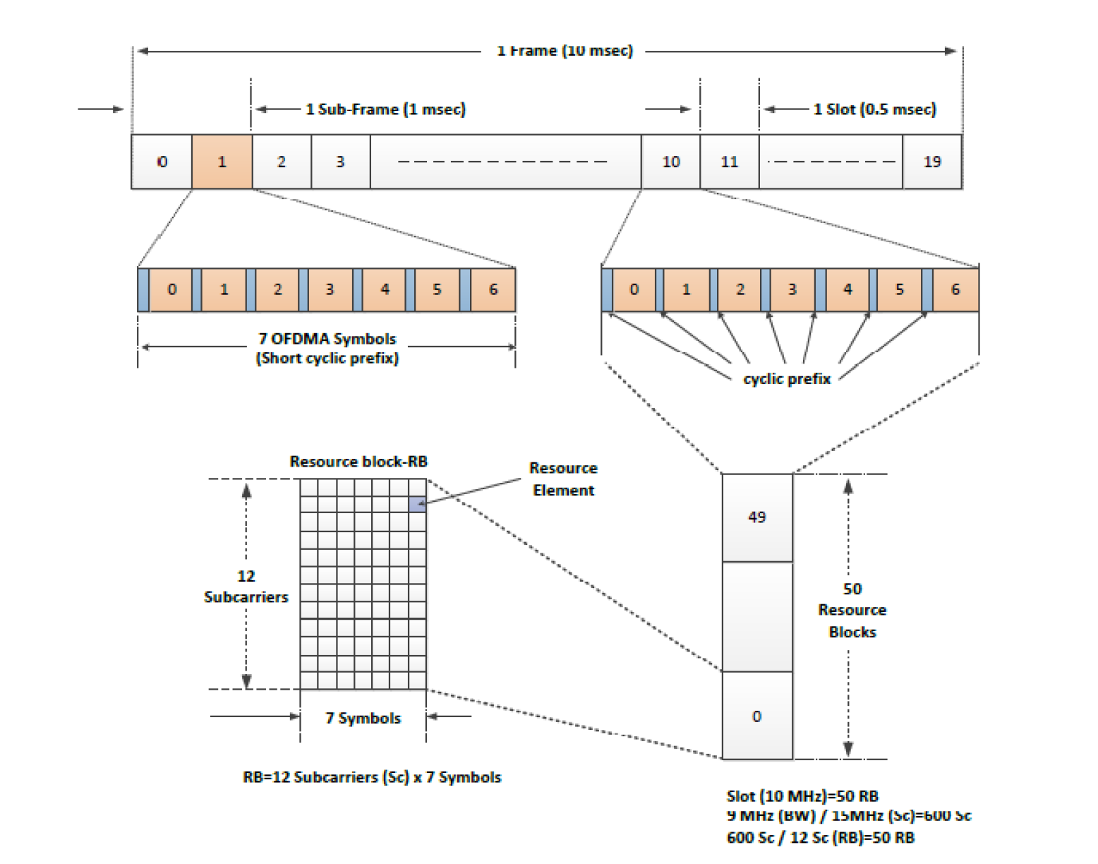
- An RB is a grid of rectangular resource elements, which consists of 12 consecutive subcarriers in the frequency domain and six or seven OFDMA symbols in the time domain.
- Thus, in an OFDM system, a RB is available in the time domain by means of OFDM symbols and in the frequency domain by means of subcarriers.
- The total number of RBs available depends on the overall transmission bandwidth of the system.
- LTE-A specification defines different exploitable bandwidths from 1.4 to 20 MHz which correspond, to 6 and 100 RBs respectively.
- Generally, in a LTE OFDM physical system, the input data stream is divided into several parallel substreams of reduced data rate and each substream is modulated and transmitted on separate orthogonal subcarriers, while the orthogonality among carriers depends on the cyclic prefix (CP) duration or the increased symbol duration improve the robustness of OFDM to delay spread.
- It means that the CP can completely eliminate inter-symbol interference when CP duration is longer than the channel delay spread.
- The minimum allocation bandwidth for a UE is one RB (180 KHz), which is carried out by the MAC scheme in each subframe as it is the sublayer which is responsible for scheduling transmission over the LTE air interface in both downlink/uplink directions.
- It must be noted that in all OFDMA systems, the scheduler decides which users are allowed to transmit and which RBs to assign to each user.
- Usually, the RB assignment to UEs operates under each 1 ms transmission time interval. The scheduler must also decide the quantity of power to apply to each RB as well as a suitable modulation and coding scheme (MCS) to be assigned to each user. Below figure shows the LTE-A radio frame structure of 10 ms duration divided into 10 subframes, each consisting of two slots of 0.5 ms.
- Due to frequency-selective interference and fading fluctuations along the spectrum, different users can experience diverse channel conditions in a given subcarrier. While the contiguous permutation group subcarriers form RB, which is also known as band-AMC, it
- enables multiuser diversity by choosing subcarriers for the mobile terminal with the best signal quality received.
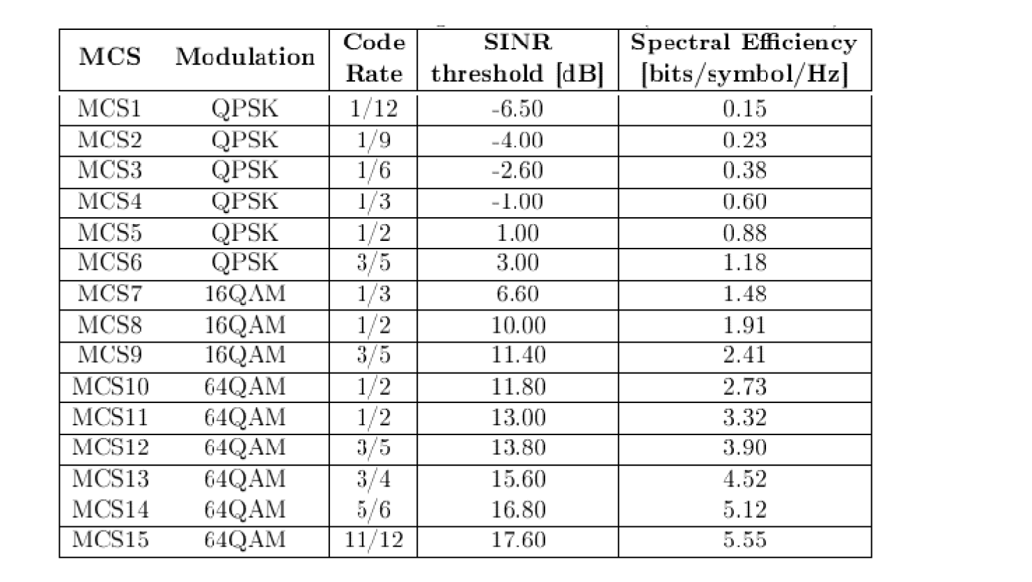
- In the OFDMA system, the transmitters need the average CQI feedback from users to apply the link adaptation, precoding preequalization, and adaptive transmission antenna diversity in order to maximize spectra efficiency. Below table describes the different MCSs supported by LTEA indexed according to CQI.
- As explained, if the channel is high fade, low order modulation is employed; conversely, if the channel is in good condition a high data rate can be achieved by employing highorder modulation.
- Similarly, code rate and transmission power can be optimized according to the instantaneous channel conditions and the required transmission rate and reliability.
- Moreover, when a mobile terminal is assigned with diversity subchannelization, it sends the reported CQ Is back to its base station. This is equivalent to the SINR level over each of the divided subcarriers or RBs.
- According to the CQI method reported, the base station can know the SINR, and then determine the appropriate MCS level for each RB. These options enable the system designer to trade mobility for throughput.
- Reference signals
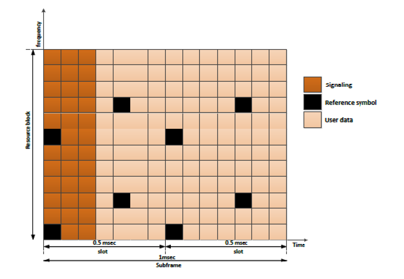
- To allow for coherent demodulation at the UE, reference symbols (or pilot symbols) are inserted in the OFDM time-frequency grid to allow for channel estimation.
- Downlink reference symbols are inserted within the first and third last OFDM symbol of each slot with a frequency domain spacing of six subcarriers (this corresponds to the fifth and fourth OFDM symbols of the slot for a normal and extended cyclic prefix, respectively) as shown in below figure for LTE system with one antenna in normal CP mode.
- Furthermore, there is frequency domain staggering of three sub carriers between the first and second reference symbols. Therefore, there are four reference symbols within each RB.
- The UE will interpolate over multiple reference symbols to estimate the channel. For two transmission antennas, reference signals are inserted from each antenna where the reference signals on the second antenna are offset in the frequency domain by three sub carriers.
- To allow the UE to accurately estimate the channel coefficients, nothing is transmitted on the other antenna at the same time-frequency location of the reference signals.
- The reference symbols have complex values, which are determined according to the symbol position as well as the cell.
- LTE specifications refer to this as a two-dimensional reference-signal sequence, which indicates the LTE cell identity. There are 510 reference signal sequences corresponding to 510 different cell identities.
- The reference signals are derived from the production of a two-dimensional pseudo-random sequence and a two-dimensional orthogonal sequence.
- There are 170 different pseudo-random sequences corresponding to 170 cell identity groups and three orthogonal sequences, each corresponding to a specific cell identity within the cell identity group.
- Reference signals are generated as the product of an orthogonal sequence and a pseudo-random numerical (PRN) sequence. Overall, there are 510 unique reference signals possible.
- A specified reference signal is assigned to each cell within a network and acts as a cell-specific identifier.