4G-LTE, LTE-A
Published:
This post covers Mobile and Wireless Networks by Khaldoun Al Agh, Guy Pujolle, and Tara Ali-Yahiya.
Basic Ideas
The 4G - Fundamental System Design
The development of Long-Term Evolution (LTE) is now finished. LTE focuses on enhancing the Universal Terrestrial Radio Access (UTRA).
LTE mobile broadband is popularly called a 4G developed by the Third Generation Partnership Project (3GPP) and adopted by the European Telecommunications Standards Institute.
In fact, LTE is not 4G but a member of 3G and should be called 3.9G but it is easier to talk about 4G. The main difference concerns the voice: 4G is a full-IP technology and the voice is transferred through a VoIP technology. In the LTE, mobile operators are using GSM for voice communications.
Obviously, it is possible to get VoIP within 3.9G technology using the data band: this is called VoLTE.
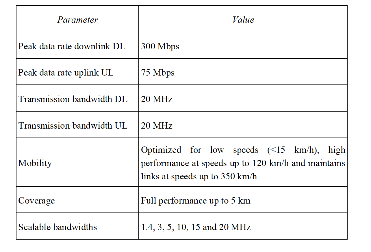
Release 6 High Speed Download Packet Access (HSDPA) levels in the downlink (100 Mbps) and two to three times the HSUPA levels in the uplink (50 Mbps).
In 2007, 3G Evolved Universal Terrestrial Radio Access progressed from the feasibility study stage to the first approved technical specifications.
By the end of 2008, the specifications were sufficiently stable for the first wave of LTE equipment in Release 8.
In order to meet this new challenge, 3GPP’s organizational partners agreed to widen 3GPP’s scope to include the development of systems beyond 3G. Some of the key features of IMT-Advanced are:
- worldwide functionality and roaming;
- compatibility of services;
- interworking with other radio access systems;
- enhanced peak data rates to support advanced services and
- applications (100 Mbit/s for high and 1 Gbps for low mobility).
Relevant features of LTE
- Orthogonal frequency-division multiplexing (OFDM) for high spectral efficiency is the basis of the physical layer: OFDM is used in downlink for robustness against multipath interference and high affinity to advanced techniques such as frequency domain channel dependent scheduling and MIMO, while Single-Carrier Frequency Division Multiple Access (SC-FDMA) is used in uplink in order to get a low peak-to-average power ratio.
- Adaptive Modulation and Coding (AMC): LTE supports a number of modulation and forward error correction coding schemes and allows the scheme to be changed on a per user and frame basis, based on channel conditions. AMC is an effective mechanism to maximize throughput in a time-varying channel. The adaptation algorithm typically calls for the use of the highest modulation and coding scheme that can be supported by the signal-to-noise and interference ratio at the receiver such that each user is provided with the highest possible data rate that can be supported in their respective links.
- Support of variable bandwidths: E-UTRAN will operate in spectrum allocations of different sizes, including 1.25, 1.6, 2.5, 5, 10, 15 and 20 MHz in both the uplink and downlink. Operation in the paired and unpaired spectrum will be supported. This scaling may be done dynamically to support user roaming across different networks that may have different bandwidth allocations.
- Support for TDD and FDD: LTE supports both time division duplexing (TDD) and frequency division duplexing. TDD is favored by a majority of implementations because of its advantages: (1) flexibility in choosing uplink-to-downlink data rate ratios, (2) ability to exploit channel reciprocity, (3) ability to implement in non-paired spectrum and (4) less complex transceiver design.
- LTE is capable of supporting very high peak data rates
- Simultaneous user support: LTE provides the ability to perform two-dimensional resource scheduling (in time and frequency), allowing the support of multiple users in a time slot; in contrast, existing 3G technology performs one-dimensional scheduling, which limits service to one user for each time slot. This capability of LTE results in a much better always-on experience.
- Efficient worldwide roaming: because LTE is the unified pre-4G standard for most 3GPP and 3GPP2 carriers worldwide, LTE devices are fundamentally easier to set up for worldwide roaming. The caveat is that the actual frequency band used by different carriers is different (thereby retaining the need for multiband devices). As a result, the wireless migration path to LTE provides greater opportunities for seamless international roaming and for global device economies of scale.
- 3GPP specified a new packet core, the Evolved Packet Core (EPC), network architecture to support the E-UTRAN through a reduction in the number of network elements, simpler functionality, improved redundancy, and for connections and handover to other fixed line and wireless access technologies, giving service providers the ability to deliver a seamless experience.
Architecture reference model
Below figure shows the LTE network reference model, which is a logical representation of the network architecture.
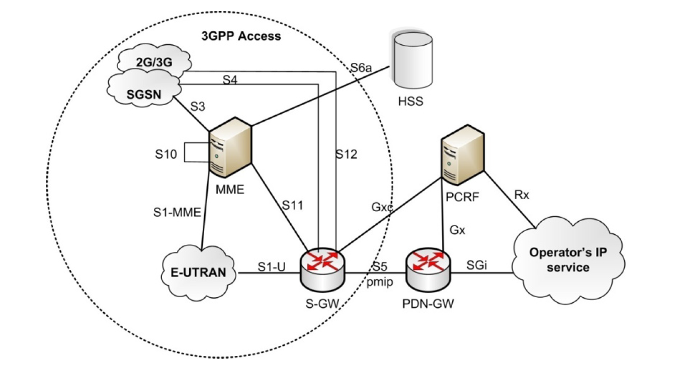
The network reference model identifies the functional entities in the architecture and the reference points between the functional entities over which interoperability is achieved.
The overall architecture has two distinct components: the access network and the core network.
The access network is E-UTRAN. The core network is all-IP core network and is fully packet switched.
Services like voice, which are traditionally circuit switched, will be handled using IP Multimedia Subsystem (IMS) network. The core network is the EPC. Network complexity and latency are reduced as there are fewer hops in both the signaling and data plane.
The EPC is designed to support non-3GPPP access supports for mobile IP. To improve system security, integrity protection and ciphering have been added via a non-access stratum plane, which is an additional layer of abstraction to protect important information like security interworking between 3GPP and non-3GPP network.
Apart from the network entities handling data traffic, EPC also contains network control entities for keeping user subscription information represented by home subscriber server, determining the identity and privileges of a user and tracking his/her activities, i.e. authorization, authentication and accounting server, and enforcing Function (PCRF). Note that E-UTRAN and EPC together constitute the evolved packet system.
Both radio access network and core network could achieve many functionalities
E-UTRAN is the air interface of 3GPP’s LTE upgrade path for mobile networks.
It is a radio access network standard meant to be a replacement of the Universal Mobile Telecommunications System, high-speed downlink packet access and high speed uplink packet access technologies specified in 3GPP releases 5 and beyond.
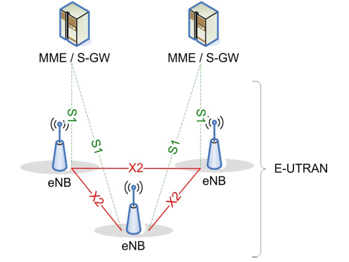
LTE’s E-UTRAN is an entirely new air interface system, which provides higher data rates and lower latency and is optimized for packet data. It uses OFDMA radio access for the downlink and SC-FDMA for the uplink. The E-UTRAN in LTE architecture consists of a single node, i.e. the eNodeB that interfaces with the user equipment (UE).
The aim of this simplification is to reduce the latency of all radio interface operations. eNodeBs are connected to each other via the X2 interface, and they connect to the packet switched core network via the S1 interface (see below figure).
radio interface into three layers: a physical layer or layer 1, the data link layer (layer 2) and the network layer or layer 3. This hierarchical stratification provides a complete vision of the radio interface, from Long-Term Evolution both the functionality associated with each of the structured layer to the protocol flow between them.
The purpose of the protocol stack is to set the services to organize the information to transmit through logical channels whose classifying parameter is the nature of the information they carry (i.e. control or traffic information) and map these logical channels into transport channels whose characteristic is how and with what the information within each logical channel is transmitted over the radio interface.
This how and with what characteristic means that for each transport channel, there is one or more associated transport formats, each defined by the encoding, interleaving bit rate and mapping onto the physical channel.
Each layer is characterized by the services provided to the higher layers or entities and the functions that support them as follows:
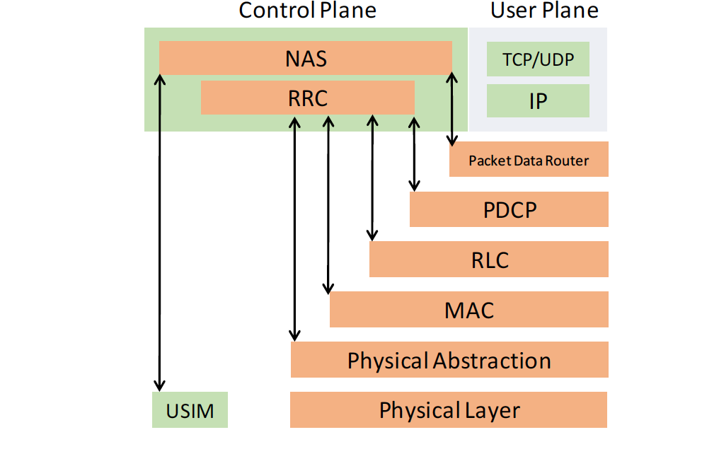
physical layer: carries all information from the medium access channel (MAC) transport channels over the air interface. Takes care of the link adaptation (adaptive modulation and code (AMC)), power control, cell search (for initial synchronization and handover purposes) and other measurements (inside the LTE system and between systems) for the radiolink control (RRC) layer
MAC: the MAC sublayer offers a set of logical channels to the RLC sublayer that it multiplexes into the physical layer transport channels. It also manages the hybrid automatic repeat request (HARQ) error correction, handles the prioritization of the logical channels for the same UE and the dynamic scheduling between UEs, etc.
RLC: it transports the Packet Data Convergence Protocols (PDCP’s) PDUs. It can work in three different modes depending on the reliability provided. Depending on this mode, it can provide HARQ error correction, segmentation, concatenation of PDUs, reordering for insequence delivery, duplicate detection, etc.
PDCP: for the RRC layer, it transports its data with ciphering and integrity protection and for the IP layer it transports IP packets, with robust header compression (ROHC), ciphering and depending on the RLC mode in-sequence delivery, duplicate detection and retransmission of its own service data units during handover.
RRC: between others, it takes care of the broadcast system information related to the access stratum and transport of the non-access stratum manages messages, paging, establishment and release of the radio resource control (RRC) connection, security key management, handover, UE measurements related to inter-system (inter-RAT) mobility, QoS, etc. Layers interfacing, with the E-UTRAN protocol stack are:
Non-access stratum: protocol between the UE and the mobility management entity (MME) on the network side (outside of EUTRAN). Between others it authenticates the UE and security control and generates part of the paging message- IP layer.